Extruded vs. Skived vs. Folded Fin vs. Bonded Fin Heat Sinks: How to Choose
Selecting the right heat sink fabrication method is one of the most critical decisions in thermal design and hardware procurement. For engineering and supply chain leaders, thermal management is rarely just about dissipate rate-it is a continuous balance between thermal resistance (°C/W), volumetric space constraints, component weight, upfront NRE tooling expenses, and unit production cost at volume.
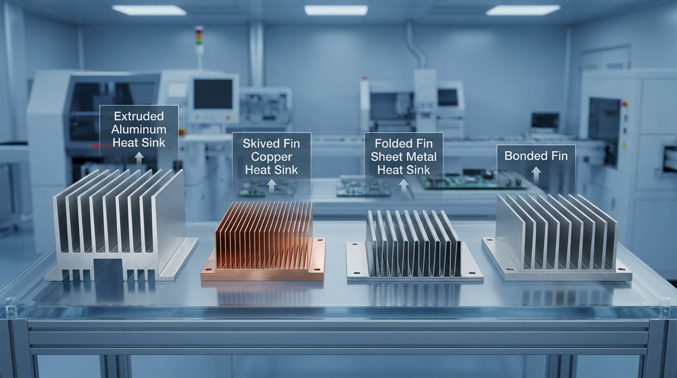
Selecting among extruded, skived, folded fin, and bonded fin heat sinks requires understanding how each manufacturing process dictates fin geometry, surface area density, and thermal interface joint integrity. While aluminum extrusion remains the default workhorse for high-volume standard cooling, demanding applications like high-density servers, power inverters, telecom modules, and automotive electronics often require the higher fin aspect ratios of skived copper, the lightweight surface area of folded fins, or the footprint flexibility of bonded fin assemblies.
This engineering and procurement guide delivers a head-to-head comparison of these four primary heat sink manufacturing technologies, breaking down technical performance, cost structures, lead times, and selection trade-offs.
Executive Comparison Matrix: Extruded vs. Skived vs. Folded vs. Bonded Fin Heat Sinks
The table below provides a high-density technical and procurement overview comparing extruded, skived, folded fin, and bonded fin heat sink constructions:
|
Performance & Procurement Parameter |
Extruded Heat Sinks |
Skived Fin Heat Sinks |
Folded Fin Heat Sinks |
Bonded Fin Heat Sinks |
|---|---|---|---|---|
|
Manufacturing Process |
Aluminum billet pushed through a hardened die |
Thin layers sliced from solid metal block & folded 90° |
Sheet metal corrugated/folded into wave fin packs |
Individual fins inserted into grooved base plate |
|
Fin Aspect Ratio Limit |
8:1 to 12:1 (up to 15:1–20:1 for custom high-ratio dies) |
40:1 to 60:1+ |
20:1 to 40:1 |
40:1 to 60:1+ |
|
Min. Fin Thickness |
1.0 mm – 1.5 mm |
0.25 mm – 0.5 mm |
0.10 mm – 0.4 mm |
0.8 mm – 1.5 mm |
|
Min. Fin Pitch (Gap) |
2.0 mm – 5.0 mm |
0.5 mm – 1.2 mm |
1.0 mm – 2.0 mm |
2.0 mm – 4.0 mm |
|
Base-to-Fin Joint Thermal Resistance |
Zero (Monolithic solid metal structure) |
Zero (Monolithic solid metal structure) |
Low to Moderate (Brazed or soldered joint) |
Moderate (Thermal epoxy or braze joint interface) |
|
Material Flexibility |
Primarily 6000-series Aluminum (6063-T5) |
Aluminum (6063/1050) or Copper (C1100) |
Aluminum, Copper, or Stainless Steel |
Hybrid (e.g., Copper fins in Aluminum base) |
|
Upfront Tooling / Die Cost (NRE) |
High ($1,000 – $5,000+ per die profile) |
Zero to Very Low (CNC blade setup) |
Moderate to High (Stamping dies & fixtures) |
Low to Moderate (Grooving tools & assembly fixtures) |
|
Prototyping Lead Time |
3 to 5 weeks (Die fabrication & sampling) |
3 to 7 business days |
2 to 4 weeks |
2 to 3 weeks |
|
Unit Production Cost in Volume |
Lowest at 1,000+ units |
Moderate to High (2×–4× higher than extrusion) |
Moderate |
High (Labor & assembly intensive) |
|
Best Application Fit |
General cooling, LED drivers, standard power supplies |
High heat-flux CPUs/GPUs, compact server modules, IGBTs |
Forced convection, weight-critical aerospace/laptops |
Large industrial power electronics, inverters, UPS |
Key Evaluation Criteria for Heat Sink Selection
When evaluating heat sink fabrication options, four core technical and procurement factors govern the final choice.
1. Fin Aspect Ratio & Volumetric Fin Density
Fin aspect ratio represents the ratio of fin height to the gap between adjacent fins (Height / Gap). Higher aspect ratios allow thermal engineers to pack significantly more heat dissipation surface area into a tight volumetric envelope.
Extrusion physics limits aluminum flow through steel dies, restricting standard extrusions to aspect ratios between 8:1 and 12:1. In contrast, skiving uses a precision wedge blade to shave thin fins directly from a solid metal block, achieving aspect ratios up to 60:1 with fin gaps as tight as 0.5 mm. According to the Boyd Thermal Fabrications Guide, maximizing aspect ratio in forced-convection environments dramatically lowers thermal resistance (°C/W) without expanding the physical footprint of the heat sink.
Key Takeaway: When space is constrained and air flow is forced, skived and folded fins provide up to 200–300% more surface area than extruded fins within the same footprint.
2. Monolithic Monometal vs. Jointed Thermal Interface Resistance
Thermal continuity from the base plate to the cooling fins dictates heat transfer efficiency.
-
Monolithic Structures (Extruded & Skived): The fins and base plate consist of one continuous piece of metal. There is zero thermal contact resistance between the base and the fins, ensuring optimal conduction heat transfer.
-
Jointed Structures (Folded & Bonded Fin): Individual fins or folded sheet packs are attached to a base plate using thermal epoxy, brazing, or soldering.
As noted in Electronic Design bonded fin analysis, epoxy bonding layers introduce a small thermal interface barrier (typically adding 8% to 12% higher thermal resistance compared to solid metal). Vacuum brazing or high-temperature soldering minimizes this joint penalty, but adds processing steps and quality control checks.
3. Tooling NRE Costs & Prototyping Lead Times
From a procurement perspective, upfront non-recurring engineering (NRE) charges and lead times heavily impact product launch schedules and cash flow:
-
Extrusion: Requires dedicated steel profile dies costing $1,000 to $5,000+ with 3–5 week lead times. Modifying a dimension requires cutting an entirely new die.
-
Skiving: Requires no custom extrusion die. CNC skiving machines utilize standardized blades, reducing prototype lead times to a few days with zero tooling investment.
-
Folded & Bonded Fin: Require forming dies or grooving cutters alongside brazing/assembly fixtures, placing tooling costs and lead times between skiving and extrusion.
Pro Tip: For fast-turnaround thermal prototyping or low-volume production runs (<500 units), skived heat sinks eliminate die charges and reduce time-to-market by weeks.
4. Unit Production Cost vs. Volume Scalability
The most economical choice at 50 units is rarely the most economical at 10,000 units.
-
High Volume (>1,000 units): Extrusions dominate. Once the die cost is amortized, automated aluminum extrusion yields the lowest unit cost per part.
-
Low-to-Medium Volume (<1,000 units): Skiving and bonded fins avoid expensive tooling die amortization, offering lower total cost for custom or short-run builds. Recent skived fin manufacturing studies highlight that skiving unit costs remain higher due to machine cycle time, but overcome extrusion tooling barriers in custom configurations.
-
In-Depth Breakdown of the 4 Heat Sink Fabrication Methods
1. Extruded Aluminum Heat Sinks (High Volume, Low Unit Cost)
Extrusion is the most widely specified heat sink manufacturing method. Heated aluminum billets (typically 6063-T5) are forced through a steel extrusion die under immense hydraulic pressure, forming a continuous linear profile that is cut to length and post-machined.
Advantages:
-
Lowest Mass-Production Unit Cost: Highly automated process yields minimal labor per part.
-
Monolithic Construction: Zero thermal contact resistance between fins and base.
-
Secondary Operation Flexibility: Profiles easily undergo CNC drilling, cross-cutting, and anodizing.
Limitations:
-
Geometry & Fin Density Limits: Cannot produce ultra-thin fins (<1.0 mm) or tight fin spacing.
-
High Tooling NRE: Requires die investment and lead time for every custom profile.
-
Material Constraint: Restricted almost exclusively to extrudable aluminum alloys; pure copper cannot be extruded into finned profiles.
2. Skived Fin Heat Sinks (Ultra-High Fin Density, Zero Joint Resistance)
Skiving is a high-precision machining technique where a specialized wedge tool slices micro-thin layers from a solid block of aluminum or copper and folds them 90 degrees upright.
Solid Billet Block - → ( Precision Skiving Blade ) - → Ultra-Thin Monolithic Fins
Advantages:
-
Maximum Fin Density & Aspect Ratio: Achieves fin thicknesses down to 0.25 mm and aspect ratios exceeding 50:1.
-
Copper Compatibility: Unlocks pure C1100 copper construction (thermal conductivity ~390 W/m·K vs Aluminum ~200 W/m·K) for extreme heat flux density.
-
Zero Thermal Joint Penalty: Monolithic block construction ensures uninterrupted heat conduction.
-
Zero Tooling Expense: Ideal for custom heat sink prototyping and short-run production.
Limitations:
-
Higher Unit Cost: Slower CNC machining cycle times increase per-unit fabrication costs compared to mass extrusion.
-
Weight: Solid copper or dense aluminum blocks add weight compared to hollow or folded sheet structures.
-
3. Folded Fin Heat Sinks (Ultra-Lightweight, High Surface Area)
Folded fin heat sinks are constructed by passing thin sheet metal (aluminum or copper, 0.1 mm to 0.4 mm thick) through a progressive folding or stamping machine to create continuous corrugated or wave-shaped fin packs. These fin packs are then furnace-brazed or soldered to a base plate or direct-contact heat pipe module.
Advantages:
-
Ultra-Lightweight Construction: Thin sheet fins maximize heat transfer surface area while dramatically reducing total assembly mass.
-
Ideal for Forced Convection & Heat Pipe Integration: Seamlessly integrates with vapor chambers, heat pipes, and duct fan cowlings.
-
Material Mixing: Allows combining copper base plates with aluminum folded fins for optimized weight-to-performance ratios.
Limitations:
-
Brazing/Soldering Quality Dependence: Improper braze coverage introduces voiding and thermal resistance at the base joint.
-
Tooling & Fixturing Cost: Progressive stamping dies and vacuum brazing fixtures require moderate tooling investments.
4. Bonded Fin Heat Sinks (Large Footprints, Extreme Height & Custom Layouts)
Bonded fin heat sinks are built by machining individual slots into a heavy base plate, inserting individual extruded or cut fins into the grooves, and securing them with high-thermal-conductivity epoxy, soldering, or vacuum brazing.
Advantages:
-
Overcomes Extrusion Size Constraints: Enables massive heat sink dimensions (exceeding 600 mm in width/length) beyond maximum extrusion die press capacities.
-
Extreme Fin Height Ratios: Supports tall fins (100 mm+) with customizable fin-to-fin spacing.
-
Hybrid Material Engineering: Enables inserting copper fins into an aluminum base plate for targeted thermal performance under high-power die hot spots.
Limitations:
-
Labor-Intensive Assembly: Manual or semi-automated fin insertion elevates unit labor costs.
-
Thermal Interface Layer: Epoxy-bonded joints introduce a thermal resistance layer that must be factored into thermal modeling.
Procurement & Sourcing Decision Framework: Which Fin Type Should You Choose?
To simplify thermal specification and sourcing, use the decision logic below based on your primary design drivers:
What is your primary design constraint?
Standard Envelope High Heat Flux High Volume >1k Tight Space Limit v v ( Choose Extruded ) ( Choose Skived )
Weight Critical Large Dimension Forced Air / Fan Custom Footprint v v ( Choose Folded ) ( Choose Bonded )
Scenario 1: Choose Extruded Heat Sinks
-
You are producing in volume (>1,000 units/year) and want the lowest possible unit price.
-
Airflow is natural convection or moderate forced air with standard fin spacing (2–5 mm).
-
You can accept a 3–5 week die fabrication lead time during NPI.
Scenario 2: Choose Skived Fin Heat Sinks
-
You are cooling high power density components (CPUs, GPUs, IGBT power modules) in compact enclosures.
-
You require pure copper fins or aspect ratios exceeding 30:1.
-
You need rapid prototypes in 3–7 days without paying extrusion die charges.
Scenario 3: Choose Folded Fin Heat Sinks
-
System mass is restricted (aerospace, mobile devices, laptop cooling).
-
You are pairing the fin pack with a heat pipe assembly or vapor chamber.
-
You operate under high static pressure forced-air cooling.
Scenario 4: Choose Bonded Fin Heat Sinks
-
Your heat sink footprint exceeds standard extrusion die diameters (>300–600 mm wide).
-
You need very tall fins (>80–120 mm) with custom thick-and-thin fin pitch variations.
-
You require a heavy-duty industrial heat sink for power distribution, traction drives, or megawatt inverters.
Partnering with Powerwinx for Custom Heat Sink Engineering & Manufacturing
Navigating thermal performance trade-offs while maintaining budget targets requires experienced manufacturing support. As a specialized thermal management manufacturer, Powerwinx thermal engineering & custom manufacturing provides complete thermal simulation, rapid prototyping, and full-scale production across all major heat sink technologies.
Whether you need quick-turn skived copper prototypes, custom extruded aluminum profiles, or complex bonded fin assemblies, Powerwinx delivers precision machining, rigorous thermal testing, and DFM (Design for Manufacturability) guidance to streamline your supply chain. Learn more about our custom heat sink prototyping and production services or consult with our engineering team for advanced air-cooled thermal management solutions.
Frequently Asked Questions
What is the difference between skived fin and extruded aluminum heat sinks?
Extruded heat sinks are formed by pushing heated aluminum through a die, resulting in lower fin density (aspect ratio 8:1–12:1) and thicker fins (≥1.0 mm), but lower unit cost in high volumes. Skived heat sinks slice fins directly from a solid metal block, achieving much higher fin density (aspect ratio up to 60:1) and thinner fins (0.25 mm), with zero die tooling costs and superior thermal performance in tight spaces.
Does a bonded fin heat sink have higher thermal resistance than a solid extruded heat sink?
Yes. Bonded fin heat sinks utilize epoxy, solder, or brazing to secure individual fins into a grooved base plate. This joint introduces a minor thermal interface barrier-typically adding 8% to 12% higher thermal resistance compared to a monolithic (single-piece) extruded or skived heat sink. However, bonded fins compensate by allowing much larger physical footprints and higher fin heights than extrusion presses can handle.
When should copper be used over aluminum for heat sinks?
Pure copper has a thermal conductivity of approximately 390 W/m·K, almost double that of standard 6063 aluminum (~200 W/m·K). Copper is recommended when heat flux density is extremely high (e.g., concentrated CPU/GPU dies or power IGBTs) and heat must spread rapidly away from the heat source. Because copper cannot be easily extruded, skived copper or folded copper fin assemblies are the preferred manufacturing methods.
How do tooling costs compare across heat sink manufacturing methods?
Extruded heat sinks require dedicated steel dies costing $1,000–$5,000+. Folded fin heat sinks require sheet metal stamping dies and brazing fixtures. Skived heat sinks require zero die tooling because they are machined on standard CNC skiving equipment using universal blades, making skiving the most cost-effective option for low-volume and prototype runs.