How to Design a Pin Fin Heat Sink for Industrial Applications
In the realm of industrial applications, efficient heat dissipation is crucial for the proper functioning and longevity of electronic components. Pin fin heat sinks have emerged as a popular solution due to their high surface area and excellent heat transfer capabilities. As a leading Pin Fin Heat Sink supplier, I am here to guide you through the process of designing an effective pin fin heat sink for industrial use.
Understanding the Basics of Pin Fin Heat Sinks
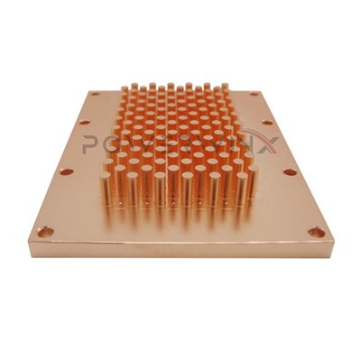
Pin fin heat sinks consist of an array of pins or fins that extend from a base plate. These pins increase the surface area available for heat transfer, allowing for more efficient cooling. The design of the pins can vary in terms of shape, size, and spacing, which all impact the heat sink's performance.
The choice of material is also a critical factor. Common materials for pin fin heat sinks include aluminum and copper. Aluminum is lightweight, cost - effective, and has good thermal conductivity. Copper, on the other hand, has even higher thermal conductivity but is more expensive and heavier.
Step 1: Determine the Heat Load
The first step in designing a pin fin heat sink is to determine the heat load of the electronic component. This involves calculating the amount of heat generated by the component during operation. The heat load is typically measured in watts (W). To accurately determine the heat load, you need to consider factors such as the power consumption of the component, its operating temperature, and the ambient temperature.
For example, if you have an industrial power amplifier that consumes 100 W of power, and the ambient temperature is 25°C, you need to design a heat sink that can dissipate this 100 W of heat effectively.
Step 2: Select the Appropriate Material
As mentioned earlier, the choice of material depends on various factors. If cost is a major concern and weight is not an issue, aluminum may be the best choice. Aluminum heat sinks, such as the Die Cast Aluminum Heat Sink, are commonly used in many industrial applications due to their affordability and decent thermal performance.
If high thermal conductivity is required, especially for applications with high heat loads, copper may be a better option. Copper soldered heat sinks, like the Copper Soldered Heat Sink, offer superior heat transfer capabilities but come at a higher cost.
Step 3: Design the Pin Geometry
The geometry of the pins plays a significant role in the heat sink's performance. The following aspects need to be considered:
- Pin Shape: Pins can have different shapes, such as circular, square, or rectangular. Circular pins are often preferred because they have a more uniform heat transfer distribution.
- Pin Size: The diameter or cross - sectional area of the pins affects the surface area available for heat transfer. Larger pins generally have a higher surface area, but they may also increase the air resistance, which can reduce the airflow over the heat sink.
- Pin Spacing: The spacing between the pins is crucial. If the pins are too close together, the airflow may be restricted, leading to poor heat transfer. On the other hand, if the pins are too far apart, the surface area available for heat transfer will be reduced.
Step 4: Consider the Airflow
Airflow is a key factor in the performance of a pin fin heat sink. There are two main types of airflow: natural convection and forced convection.
- Natural Convection: In natural convection, the heat causes the air around the heat sink to rise, creating a natural flow of air. This type of airflow is suitable for low - power applications where the heat load is relatively small.
- Forced Convection: For high - power applications, forced convection is often required. This involves using a fan or blower to force air over the heat sink. When designing a heat sink for forced convection, you need to consider the direction and speed of the airflow. The pins should be aligned in the direction of the airflow to minimize air resistance.
Step 5: Optimize the Design
Once you have designed the basic pin fin heat sink, it is important to optimize the design to improve its performance. This can be done through computer - aided design (CAD) and computational fluid dynamics (CFD) simulations.
CAD software allows you to create a 3D model of the heat sink and analyze its geometry. CFD simulations can be used to predict the airflow and heat transfer characteristics of the heat sink. By making adjustments to the pin geometry, spacing, and material, you can optimize the design to achieve the best possible performance.
Step 6: Manufacturing and Testing
After the design is finalized, the heat sink needs to be manufactured. There are several manufacturing processes available, such as extrusion, machining, and die - casting. The choice of manufacturing process depends on the complexity of the design and the material used.
Once the heat sink is manufactured, it is important to test its performance. This can be done using thermal testing equipment to measure the temperature of the heat sink under different operating conditions. If the performance does not meet the requirements, further adjustments may need to be made to the design.
Conclusion
Designing a pin fin heat sink for industrial applications requires a comprehensive understanding of heat transfer principles, material properties, and manufacturing processes. By following the steps outlined above, you can design an effective heat sink that meets the specific requirements of your industrial application.
As a Pin Fin Heat Sink supplier, we have the expertise and experience to help you design and manufacture high - quality heat sinks. Whether you need a Copper Soldered Heat Sink, a Die Cast Aluminum Heat Sink, or a Stamped Fin Heat Sink, we can provide you with customized solutions.


If you are interested in purchasing pin fin heat sinks for your industrial applications, please feel free to contact us for further discussions and procurement negotiations. We look forward to working with you to meet your thermal management needs.
References
- Incropera, F. P., & DeWitt, D. P. (2002). Fundamentals of Heat and Mass Transfer. John Wiley & Sons.
- Bergman, T. L., Lavine, A. S., Incropera, F. P., & DeWitt, D. P. (2011). Introduction to Heat Transfer. John Wiley & Sons.